設定 CXP-12 Interface Card#
資訊
本主題涵蓋基本使用案例。如需有關介面卡軟體功能的深入資訊,請參閱 acquisition applets PDF 說明文件。
在以下情況下,設定介面卡特別有用:
- 您想要變更 Applet 以供介面卡使用。
- 您想要透過介面卡觸發所連接的 Basler boost CXP-12 相機。
- 您想要在介面卡上執行去拜爾 (Debayering),以提高成像系統的效能。
- 您想要使用相機上無法使用的輸出格式,例如 16-bit mono 格式。
- 您想要設定觸發訊號,以便由介面卡接收或傳送。
限制
在所有 Applet 中,無法配置大於 4 GB 的緩衝區。即使 Applet 允許更大的緩衝區大小,由於驅動程式和韌體的限制,您也無法配置大於 4 GB 的緩衝區。
您可以透過以下方式計算緩衝區大小:
緩衝區大小 = 影像高度 * 影像寬度 * (像素寬度 / 8)。
對於 RGB 影像:緩衝區大小 = (影像高度 * 影像寬度 * (像素寬度 / 8)) * 3。
可用的面陣掃描 Applet 與預設 Applet#
根據介面卡型號,提供以下 applet 且預設會進行設定:
| Applet 名稱 | 適用於介面卡 | 介面卡上的預設 applet |
|---|---|---|
| Acq_SingleCXP12Area | 1C、2C、4C | 1C |
| Acq_DualCXP12Area | 2C、4C | 2C |
| Acq_TripleCXP12Area | 4C | - |
| Acq_QuadCXP12Area | 4C | 4C |
除了 Acquisition Applets 之外,您也可以使用 Enhanced Applets。Enhanced Applets 為原型版本,僅限透過您當地的 Basler 業務代表或現場應用工程師提出請求時方可取得。所有 Enhanced Applets 皆具備以下附加功能:
- Binning(目前僅限單色)最高可達 4x4
- 適用於單色相機的 Block-based flat field correction (FFC)
- PGI high quality Debayering 與影像品質提升
可用的線陣掃描 Applet#
根據介面卡型號,可提供以下 applet。請注意,預設 applet(即預設載入的 applet)一律為面陣掃描 applet。因此,如果您想使用線陣掃描 applet,必須先如 Changing the Applet 中所述將其載入。
| Applet 名稱 | 適用於介面卡 |
|---|---|
| Acq_SingleCXP12Line | 1C、2C、4C |
| Acq_DualCXP12Line | 2C、4C |
| Acq_TripleCXP12Line | 4C |
| Acq_QuadCXP12Line | 4C |
文件#
以下章節提供採集 applet 文件的連結:
CXP-12 Interface Card 1C#
| GenTL | Fglib |
|---|---|
| Acq_SingleCXP12x1Area PDF | Acq_SingleCXP12x1Area PDF |
| Acq_SingleCXP12Line PDF | Acq_SingleCXP12Line PDF |
| Frame Grabber Test Applet PDF | Frame Grabber Test Applet PDF |
CXP-12 Interface Card 2C#
CXP-12 Interface Card 4C#
選擇正確的 Applet#
如果您僅使用單通道 (1-CXP) 相機,預設 applet 將隨時適用於您的應用,且您無需進行變更。
然而,如果您使用的是多通道(例如 2-CXP 或 4-CXP)相機,則必須為您的相機設定選擇正確的 applet。否則,相機可能無法運作,或相機效能可能會大幅降低。
哪一個 applet 才正確,取決於相機數量、每台相機的通道數以及所需的 ROI 遞增尺寸。
ROI 遞增尺寸取決於影像前處理的 Parallelism,因此會因相機和擷取卡而異。
CXP-12 Interface Card 1C#
適用於 CXP-12 Interface Card 1C 的面陣掃描 Applet#
| 最大相機數量 | 1 通道相機數量 | 2 通道相機數量 | 4 通道相機數量 | Applet | ROI 步進尺寸 [px] |
|---|---|---|---|---|---|
| 1 | 1 | Acq_SingleCXP12x1Area | x: 4 y: 1 |
適用於 CXP-12 Interface Card 1C 的線陣掃描 Applet#
| 最大相機數量 | 1 通道相機數量 | 2 通道相機數量 | 4 通道相機數量 | Applet | ROI 步進尺寸 [px] |
|---|---|---|---|---|---|
| 1 | 1 | Acq_SingleCXP12Line | x: 4 y: 1 |
CXP-12 Interface Card 2C#
適用於 CXP-12 Interface Card 2C 的面陣掃描 Applet#
| 最大相機數量 | 1 通道相機數量 | 2 通道相機數量 | 4 通道相機數量 | Applet | ROI 步進尺寸 [px] |
|---|---|---|---|---|---|
| 2 | 1 | Acq_DualCXP12Area | x: 8 y: 1 | ||
| 2 | 2 | Acq_DualCXP12Area | x: 8 y: 1 | ||
| 1 | 1 | Acq_SingleCXP12Areaa | x: 16 y: 1 | ||
| 1 | 1 | Acq_SingleCXP12Area | x: 16 y: 1 |
適用於 CXP-12 Interface Card 2C 的線陣掃描 Applet#
| 最大相機數量 | 1 通道相機數量 | 2 通道相機數量 | 4 通道相機數量 | Applet | ROI 步進尺寸 [px] |
|---|---|---|---|---|---|
| 2 | 1 | Acq_DualCXP12Line | x: 8 y: 1 | ||
| 2 | 2 | Acq_DualCXP12Line | x: 8 y: 1 | ||
| 1 | 1 | Acq_SingleCXP12Lineb | x: 16 y: 1 | ||
| 1 | 1 | Acq_SingleCXP12Line | x: 16 y: 1 |
CXP-12 Interface Card 4C#
適用於 CXP-12 Interface Card 4C 的面陣掃描 Applet#
| 最大相機數量 | 1 通道相機數量 | 2 通道相機數量 | 4 通道相機數量 | Applet | ROI 步進尺寸 [px] |
|---|---|---|---|---|---|
| 4 | 1 | Acq_QuadCXP12Area | x: 8 y: 1 | ||
| 4 | 2 | Acq_QuadCXP12Area | x: 8 y: 1 | ||
| 4 | 3 | Acq_QuadCXP12Area | x: 8 y: 1 | ||
| 4 | 4 | Acq_QuadCXP12Area | x: 8 y: 1 | ||
| 3 | 1 | Acq_TripleCXP12Areac | x: 16/8/8 y: 1 | ||
| 3 | 2 | Acq_TripleCXP12Areac | x: 16/8/8 y: 1 | ||
| 3 | 3 | Acq_TripleCXP12Areac | x: 16/8/8 y: 1 | ||
| 3 | 1 | Acq_TripleCXP12Aread | x: 16/8/8 y: 1 | ||
| 3 | 1 | 1 | Acq_TripleCXP12Area | x: 16/8/8 y: 1 | |
| 3 | 2 | 1 | Acq_TripleCXP12Area | x: 16/8/8 y: 1 | |
| 2 | 1 | Acq_DualCXP12Areac | x: 16 y: 1 | ||
| 2 | 2 | Acq_DualCXP12Areac | x: 16 y: 1 | ||
| 2 | 1 | 1 | Acq_DualCXP12Area | x: 16 y: 1 | |
| 2 | 1 | Acq_DualCXP12Areae | x: 16 y: 1 | ||
| 2 | 2 | Acq_DualCXP12Area | x: 16 y: 1 | ||
| 1 | 1 | Acq_SingleCXP12Areac | x: 32 y: 1 | ||
| 1 | 1 | Acq_SingleCXP12Areaf | x: 32 y: 1 | ||
| 1 | 1 | Acq_SingleCXP12Area | x: 32 y: 1 |
適用於 CXP-12 Interface Card 4C 的線陣掃描 Applet#
| 最大相機數量 | 1 通道相機數量 | 2 通道相機數量 | 4 通道相機數量 | Applet | ROI 步進尺寸 [px] |
|---|---|---|---|---|---|
| 4 | 1 | Acq_QuadCXP12Line | x: 8 y: 1 | ||
| 4 | 2 | Acq_QuadCXP12Line | x: 8 y: 1 | ||
| 4 | 3 | Acq_QuadCXP12Line | x: 8 y: 1 | ||
| 4 | 4 | Acq_QuadCXP12Line | x: 8 y: 1 | ||
| 3 | 1 | Acq_TripleCXP12Lineg | x: 16/8/8 y: 1 | ||
| 3 | 2 | Acq_TripleCXP12Lineg | x: 16/8/8 y: 1 | ||
| 3 | 3 | Acq_TripleCXP12Lineg | x: 16/8/8 y: 1 | ||
| 3 | 1 | Acq_TripleCXP12Lineh | x: 16/8/8 y: 1 | ||
| 3 | 1 | 1 | Acq_TripleCXP12Line | x: 16/8/8 y: 1 | |
| 3 | 2 | 1 | Acq_TripleCXP12Line | x: 16/8/8 y: 1 | |
| 2 | 1 | Acq_DualCXP12Lineg | x: 16 y: 1 | ||
| 2 | 2 | Acq_DualCXP12Lineg | x: 16 y: 1 | ||
| 2 | 1 | Acq_DualCXP12Line | x: 16 y: 1 | ||
| 2 | 1 | 1 | Acq_DualCXP12Linei | x: 16 y: 1 | |
| 2 | 2 | Acq_DualCXP12Line | x: 16 y: 1 | ||
| 1 | 1 | Acq_SingleCXP12Line | x: 32 y: 1 | ||
| 1 | 1 | Acq_SingleCXP12Line | x: 32 y: 1 | ||
| 1 | 1 | Acq_SingleCXP12Line | x: 32 y: 1 |
變更 Applet#
介面卡上執行的 Applet 定義了其功能。對於特定的相機設置,您可能需要更改預設的 Applet。
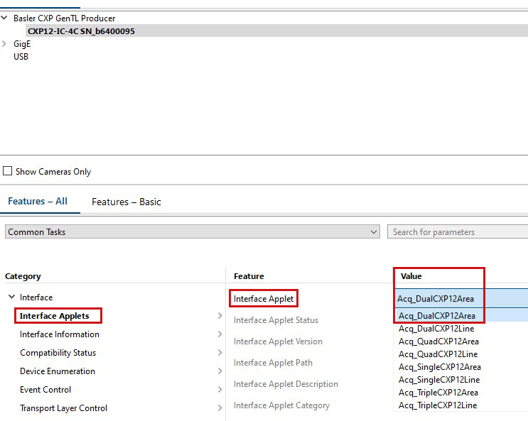
若要變更 pylon 中介面卡所使用的 Applet,請設定 InterfaceApplet 參數設為要載入的 applet 名稱,例如: Acq_DualCXP12Area:
使用介面卡來觸發 Basler boost CXP-12 相機#
資訊
本節僅在您明確希望透過介面卡觸發相機時適用。通常,相機是透過相機的 I/O 連接器進行觸發。如需詳細資訊,請參閱 觸發式影像擷取。
如需此處參照之參數的詳細說明,請參閱面陣掃描 applet 說明文件。
硬體觸發(外部)#
啟用外部觸發後,您可以將觸發輸入訊號傳送至介面卡,然後介面卡會將這些訊號轉發至 Basler boost 相機。
若要將介面卡設定為外部硬體觸發:
- 將
AreaTriggerMode參數設為External. - 將
TriggerInSource參數設為所需的 "Front GPI" 輸入線。
例如,如果您想要使用 GPI0(介面卡上的針腳 11 與 12)進行外部觸發,請將參數設為FrontGpiTriggerSource0. - 將
TriggerCameraOutSelect參數設為對應的 "Bypass" 選項。
例如,如果您選擇了FrontGpiTriggerSource0,請將TriggerCameraOutSelect參數設為BypassFrontGpi0. - 將
TriggerState參數設為Active. - 如有必要,請按照下方所述設定觸發訊號。
所有觸發訊號都將轉發至相機的來源訊號 CxpTrigger0 和 CxpTrigger1。這些訊號可用於各種用途。最常見的應用情境是影像擷取。請參閱 下方的範例.
硬體觸發(內部)#
啟用內部觸發後,介面卡將以指定的頻率在內部產生觸發訊號。所有外部觸發訊號都將被忽略。
若要將介面卡設定為內部硬體觸發:
- 將
AreaTriggerMode參數設為Generator. - 將
TriggerOutputFrequency參數設為所需的觸發輸出頻率。例如,如果您將參數設為 8,介面卡將每秒產生 8 個觸發訊號。 - 將
TriggerCameraOutSelect參數設為所需的輸出線,例如PulseGenerator0. - 將
TriggerState參數設為Active.
現在,每當您開始影像擷取時,介面卡就會以指定的頻率產生觸發訊號。
所有觸發訊號都將轉發至相機的來源訊號 CxpTrigger0 和 CxpTrigger1。這些訊號可用於各種用途。最常見的應用情境是影像擷取。請參閱 下方的範例.
範例:使用觸發訊號進行影像擷取#
- 在相機上,將
TriggerSelector參數設為FrameStart. - 將
TriggerMode參數設為On. - 將
ExposureMode參數設為Timed. - 將
TriggerSource參數設為CxpTrigger0或CxpTrigger1.
現在,每當介面卡接收或產生觸發訊號時,相機就會擷取一張影像。
資訊
您可以將觸發訊號用作任何可由訊號來源控制的 Basler boost 相機功能的來源。例如,設定 CounterTriggerSource 參數設為 CxpTrigger0 可讓您使用介面卡來控制 Counter 功能。
在介面卡上執行去拜爾 (Debayering)#
透過 CXP-12 Interface Card 1C,您可以在介面卡上執行去拜爾 (debayering)。這能降低相機與主機電腦的運算負載。
若要這樣做:
- 啟動 pylon Viewer 並建立與介面卡和相機的連線。
- 使用功能樹狀結構進行下列設定:
- 在相機上,將 Pixel Format 選項設定為 Bayer pixel format,例如 Bayer RG 12。
- 導覽至 Device Transport Layer 並停用 Automatic Format Control 選項。
這可讓您獨立於相機所使用的像素格式來設定輸出格式。 - 在介面卡上,將 OutputFormat 選項設定為對應的 RGB 像素格式。
其位元深度必須是 Bayer 像素格式位元深度的三倍。例如,Bayer RG 12 (相機) = Color 36 bit (介面卡)。
現在,介面卡將會在相機的原始影像資料上執行去拜爾,並輸出 RGB 影像資料。
資訊
請確保您在上述步驟 3 中設定了正確的 RGB 像素格式。否則,將無法正常擷取影像。
使用相機不支援的輸出格式#
Basler boost 相機能以多種像素格式輸出影像資料,例如 Bayer RG 8 或 RGB 8。如需詳細資訊,請參閱 pixel format 主題。
如果相機不提供您所需的像素格式,且您也想避免在主機電腦上進行影像轉換,您或許可以使用介面卡所提供的其中一種像素格式。
介面卡提供下列格式:
| Gray8bit | Gray10bit | Gray12bit | Gray16bit |
| Color24bit | Color30bit | Color36bit | Color48bit |
| Bayergr8 | Bayergr10 | Bayergr12 | Bayergr16 |
| Bayerrg8 | Bayerrg10 | Bayerrg12 | Bayerrg16 |
| Bayergb8 | Bayergb10 | Bayergb12 | Bayergb16 |
| Bayerbg8 | Bayerbg10 | Bayerbg12 | Bayerbg16 |
若要使用相機不支援的輸出格式:
- 在相機上,將
PixelFormat將 parameter 設定為所需的相機 Pixel Format,例如:Mono12. - 在介面卡上,將
AutomaticFormatControl參數設為false.
這可讓您獨立於相機所使用的 Pixel Format 來設定輸出格式。 - 在介面卡上,將
Format將 parameter 設定為所需的輸出格式,例如:Gray16bit.
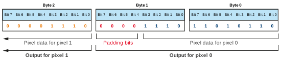
根據上述範例數值,介面卡將根據 12-bit 相機影像資料輸出 16-bit 影像資料。將會如以下圖示插入填補位元(零)。
使用 gpioTool 設定觸發訊號#
透過 gpioTool 命令列工具,您可以設定介面卡接收或傳送之觸發訊號的實體 Property:
- 您可以設定輸入線路以接收單端或差動訊號。
- 您可以設定輸入線路以在上拉或下拉模式下運作。
- 您可以指定是否應反相輸出訊號。
gpioTool 包含在 pylon Software Suite 中。
若要啟動工具:
- 開啟命令提示字元視窗 (Windows) 或終端機視窗 (Linux)。
-
切換至 pylon 安裝目錄下的 bin 目錄:
- Windows (64 bit):%programfiles%\Basler\pylon x\Runtime\x64\pylonCXP\bin
- Windows (32 bit):%programfiles%\Basler\pylon x\Runtime\Win32\pylonCXP\bin
- Linux:/opt/pylon/lib/pylonCXP/bin
-
使用以下描述的選項啟動 gpioTool。
選項#
以下選項可用:
-b [board_index]
指定要定址系統中的哪個 CXP-12 Interface Card。除了以下選項外,此參數為必填: -h.
的值範圍 [board_index] 是安裝在您系統中的所有 CXP-12 Interface Card 板卡的索引編號。如果您的系統中只有一張 CXP-12 Interface Card,請將 [board_index] 設為 0。
-b [board_index] -g
顯示指定的 CXP-12 Interface Card 的目前 GPIO bank 設定。
-b [board_index] -v
顯示詳細輸出的目前 GPIO bank 設定。
-b [board_index] -s [bank]:[settings]
設定指定的 CXP-12 Interface Card 上的 GPIO bank。
[bank] 指定 GPIO bank 的索引編號。在 CXP Interface Card 1C 上,剛好有一個 GPIO bank(前置 GPIO)可用。因此,請務必設定 [bank] 設為 0。
[settings] 進行設定。請參閱下方的 .
-h
顯示說明。
Settings#
對於 [settings] 部分中的 -b [board_index] -s [bank]:[settings],提供以下設定:
| 設定 | Value | 結果 |
|---|---|---|
[signal] | se | 將輸入線路設定為接收單端信號。 |
[signal] | ds | 將輸入線路設定為接收差動信號。 |
[pull-up-down] | pu | 將輸入線路配置為上拉 (pull-up) 模式運行。j |
[pull-up-down] | pd | 將輸入線路配置為下拉 (pull-down) 模式運行。k |
[inversion] | ni | 停用輸出線路的取反功能。 |
[inversion] | in | 啟用輸出線路的取反功能。 |
您必須以以下格式輸入設定: [signal],[pull-up-down],[inversion]。範例: ds,pu,ni
或者,您可以設定 [settings] 設定為 default。這會 重設組態 某個 GPIO 組 (bank)。
範例#
gpioTool -b 0 -s 0:ds,pu,ni
此命令會按如下方式設定介面卡:
-b 0:設定板卡 0 上的 GPIO。-s:開始實際的組態設定。0::設定 GPIO 組 0(前置 GPIO)。ds,pu,ni:將前置 GPIO 設定為接收差動訊號 (ds)、以上拉 (pu) 模式運作,以及發送未取反的輸出訊號 (ni)。
重設組態#
若要將板卡和 GPIO 組重設為預設設定,請啟動 gpioTool 並使用 [settings] 設為時,參數未正確呈現為灰色 default:
gpioTool -b [board_index] -s [bank]:default
範例: gpioTool -b 0 -s 0:default
範例程式碼#
// Select the Acq_SingleCXP12Area applet
camera.GetTLParams().InterfaceApplet.SetValue(Acq_SingleCXP12Area);
// Configure the interface card for external triggering
camera.GetTLParams().AreaTriggerMode.SetValue(AreaTriggerMode_External);
camera.GetTLParams().TriggerInSource.SetValue(TriggerInSource_FrontGpiTriggerSource0);
camera.GetTLParams().TriggerCameraOutSelect.SetValue(TriggerCameraOutSelect_BypassFrontGpi0);
camera.GetTLParams().TriggerState.SetValue(TriggerState_Active);
// Configure the interface card for internal triggering
camera.GetTLParams().AreaTriggerMode.SetValue(AreaTriggerMode_Generator);
camera.GetTLParams().TriggerOutputFrequency.SetValue(8);
camera.GetTLParams().TriggerCameraOutSelect.SetValue(TriggerCameraOutSelect_PulseGenerator0);
camera.GetTLParams().TriggerState.SetValue(TriggerState_Active);
// Use the external or internal trigger signals for image acquisition
camera.TriggerSelector.SetValue(TriggerSelector_FrameStart);
camera.TriggerMode.SetValue(TriggerMode_On);
camera.ExposureMode.SetValue(ExposureMode_Timed);
camera.TriggerSource.SetValue(TriggerSource_CxpTrigger0);
// Perform debayering on the interface card (Bayer RG 12 --> RGB 36 bit)
camera.PixelFormat.SetValue(PixelFormat_BayerRG12);
camera.GetTLParams().AutomaticFormatControl.SetValue(false);
camera.GetTLParams().Format.SetValue(Format_Color36bit);
// Configure the interface card to output 16-bit mono image data based on
// 12-bit mono image data from the camera
camera.PixelFormat.SetValue(PixelFormat_Mono12);
camera.GetTLParams().AutomaticFormatControl.SetValue(false);
camera.GetTLParams().Format.SetValue(Format_Gray16bit);
此範例程式碼僅提供 C++ 語言版本。
您也可以使用 pylon Viewer 來輕鬆設定參數。
-
僅在您需要鏡射像素超過 8K 的影像時建議使用。否則,請使用 DualCXP12Area。
-
僅在您需要鏡射像素超過 21840 的影像時建議使用。否則,請使用 DualCXP12Line。
-
只有在需要鏡射大於 8K 像素的影像時才建議使用。否則,請使用 QuadCXP12Area。
-
不建議使用,請改用 DualCXP12Area。
-
只有在需要鏡射大於 8K 像素的影像時才建議使用。否則,請使用 TripleCXP12Line(僅限單通道相機)。
-
只有在需要鏡射大於 21840 像素的影像時才建議使用。否則,請使用 DualCXP12Area。
-
只有在需要鏡射大於 8K 像素的影像時才建議使用。否則,請使用 QuadCXP12Line。
-
不建議使用,請改用 DualCXP12Line。
-
只有在需要鏡射大於 8K 像素的影像時才建議使用。否則,請使用 TripleCXP12Line(僅限單通道相機)。
-
在大多數應用中,您都需要設定此模式。介面卡會啟用 10 kΩ 上拉電阻以接收來自 NPN 電晶體(開集極、開汲極)的訊號。
-
介面卡會啟用 10 kΩ 下拉電阻以接收來自 PNP 電晶體(開射極、開源極)的訊號。