Rectangle Measurements PRO vTool#
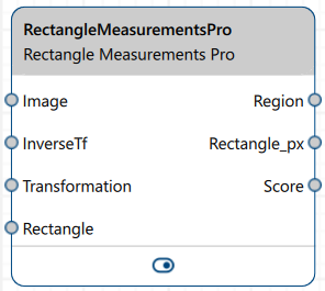
「矩形測量 Pro」vTool 可透過「影像」輸入接腳接收影像,並透過其輸出接腳輸出所偵測到的矩形相關資訊。
若您在測量前使用「校準 vTool」,並將兩個 vTool的變換輸出/輸入接腳相互連接,則「校準 vTool」所提供的變換資料將使「矩形測量 Pro vTool」能夠以世界座標系中的公尺為單位輸出測量結果(接尾詞為_m的輸出接腳將可使用)。
如果您在測量前使用 Matching vTool 與 Image Alignment vTool,您可以測量出現在與參考影像不同位置的物件。透過 InverseTf 輸入接腳提供的轉換可讓 vTool 輸出原始輸入影像的測量結果。
如欲購買 Rectangle Measurements Pro vTool 的授權,請造訪Basler 網站。此授權亦包含以下 vTools:
- Measurements Basic vTool
- Circle Measurements Pro vTool
- Ellipse Measurements Pro vTool
- Line Measurements Pro vTool
運作原理#
透過定義一個測量物件,並將其調整為與輸入影像中欲測量的形狀相符,您便能取得以下資訊:
- 顯示該區域形狀的視覺化圖像
- 長方形的尺寸
- 形狀擬合分數
形狀設定#
測量物件定義了 vTool 用以偵測待測量形狀邊緣的區域。載入影像後,系統會顯示一個預設的測量物件,其形狀為矩形,並包含內框與外框。這兩個框之間的距離等於形狀公差值乘以 2。
輸入影像中的目標形狀輪廓必須位於這兩個框線之間。若設定較大的容差值,即可容許目標形狀在尺寸上有所變化。
您可以透過拖曳矩形的控制點,或手動在對應的輸入框中輸入所需數值,或使用提供的滑桿,來移動、調整大小及旋轉測量物件。此外,您也可以透過「矩形」輸入接點提供一個矩形。若採用此方式,則「形狀設定」區域中的選項將無法使用(唯讀)。
「形狀公差」的數值只能手動輸入。即使使用「矩形」輸入接腳,此選項仍可使用。
設定範例#
除了被測物件的尺寸和位置外,您還可以指定樣本區段的數量與寬度。在這些樣本區段內,vTool 會偵測可能的邊緣候選點,並將其擬合至幾何形狀。使用的區段越多,測量結果就越穩健。缺點是,區段數量過多會降低處理速度。
預設情況下,區段會以最小間隙和最小重疊的方式均勻分布,且「樣本區段數」與「樣本區段寬度」這兩項選項是相互關聯的。若您變更其中一項,另一項會隨之調整。若您停用此關聯,即可自由調整數量與寬度。在此情況下,唯一的限制是測量對象的大小。
- 已連結選項:

- 未連結選項:

透過指定適當的「樣本公差」值,您可以考慮波浪度或潛在形狀變形的程度。為使形狀擬合成立,採樣邊緣點必須位於此公差範圍內。
透過「最低分數」選項,您可以指定預期內點的比例,也就是說,必須有多少個樣本支持該形狀擬合。
偵測設定#
邊緣被定義為梯度在局部範圍內絕對值最強的位置。通常,剖面訊號會透過低通濾波器進行平滑處理。請使用「平滑」選項來設定濾波器的強度。
The local extrema of the gradient must be stronger than the Threshold value specified to be accepted as an edge. Try different threshold values to find the optimum setting. The optimum is somewhere between an upper value where all target edges are just detected and a lower value where unwanted edges are not detected anymore.
邊緣具有正向或負向的漸變。若邊緣漸變為正向,則過渡方向為由暗至亮;若邊緣漸變為負向,則過渡方向為由亮至暗。若您預期在應用程式中僅會遇到某一種類型的過渡,請據此設定「過渡」選項。透過「均勻」過渡選項,您可以確保僅選取具有相同過渡類型的邊緣。
配合「過渡」功能,「選取」選項可讓您指定應選用哪些邊緣,以將測量物件貼合至形狀上。為使應用程式更具穩健性,請僅選取所需的邊緣類型,而非將此選項設定為「全部」。此處可選取的第一個、最後一個,或是(就梯度大小而言)最強的邊緣。
資訊
vTool 會從形狀的內側往外側,讀取樣本區段的灰度值曲線。
Using Calibration#
The resulting positions and distances can also be output in world coordinates in meters. To achieve this, connect the Transformation output pin of the Calibration vTool to the Measurements vTool's Transformation input pin.
資訊
The measurement plane is the plane in which the edges to be measured lie in the 3-dimensional world. In every image to process, the edges have different positions within the measurement plane. Register this measurement plane by placing the calibration plate's surface in this measurement plane.
You have to use the same calibration configuration for setting up the Measurements vTool as for the actual processing.
Using Image Alignment#
「矩形測量 Pro」vTool 需要待測形狀始終保持在相同位置,也就是說,必須在定義的形狀公差範圍內。否則,檢測將會失敗。為了提供您更大的靈活性,您可以將「匹配」vTool 和「Image Alignment 」vTool加入您的製程配方中。
配對功能能夠偵測輸入影像中與參考影像相比,位於不同位置的目標形狀。它會計算並輸出對齊變換資料,接著「Image Alignment 」vTool 會利用這些資料,向「Rectangle Measurements Pro」vTool 提供一張已對齊的輸入影像,使該形狀在影像中的位置與參考影像中的位置一致。此時,即可對該形狀進行測量。
「Rectangle Measurements Pro」vTool 亦會接收逆變換資料,藉此可針對輸入影像(而非對齊後的影像)輸出正確的位置資料。
資訊
若InverseTf輸入腳位未連接,則形狀的參數將以對齊後的影像為基準進行輸出。
若InverseTf輸入腳位已連接,則形狀的參數將以「Image Alignment 」vTool 的輸入影像為基準進行輸出。
無論您是否使用「Calibration」vTool,此規則均適用。
設定 vTool#
要設定「Rectangle Measurements Pro」vTool:
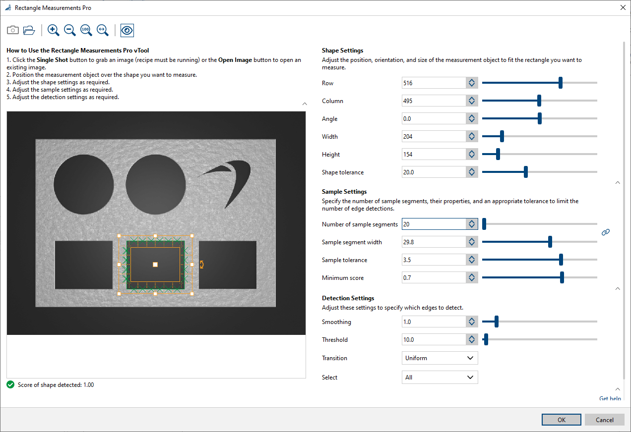
- 在vTool 設定區域的「配方管理」窗格中,按一下「開啟設定」或雙擊該 vTool。
此時將開啟「Rectangle Measurements Pro」對話方塊。 - 擷取或開啟影像。
- 在「形狀設定」區域中,請透過手動輸入數值,或使用測量矩形的控制點來移動、調整大小及旋轉,以定義測量物件,使其與影像中您欲測量的目標形狀相符。
此外,您亦可連接「矩形」輸入引腳以提供測量物件。
水平測量物件的角度為 0。 - 在「樣本設定」區域中,請指定樣本區段的數量與寬度,以及樣本容差和所需的最低分數。
- 點擊「顯示/隱藏詳細資訊」按鈕,即可在圖像中顯示樣本區段與樣本點。
- In the Detection Settings area, set Smoothing and Threshold to detect the edges in a robust and precise manner.
- Set Transition and Select such that only the target edges are selected.
You can view the result of the measurement in a pin data view. Here, you can select which outputs to display.
Inputs#
Image#
可直接從「相機」vTool 或任何能輸出影像的 vTool(例如「Image Format Converter 」vTool)接收影像。
- 資料類型:圖片
- 影像格式:8 位元至 16 位元單色或彩色影像。彩色影像會在內部轉換為單色影像。
InverseTf#
Accepts the inverse transformation data of the alignment transformation. With this, the vTool can output correct position data for the input image instead of the aligned image.
- Data type: Transformation Data
Rectangle#
Accepts a rectangle to define the measurement rectangle. If this input pin is connected, the rectangle parameters from the input are used and the rectangle settings in the dialog are read-only.
- Data Type: RectangleF
Transformation#
接收來自 Calibration vTool 的轉換資料。
- Data type: Transformation Data
Outputs#
Region#
回傳該形狀的區域。
- 資料類型:Region
Rectangle_px#
回傳圖形在影像像素座標系(行/列)中的尺寸。
- 資料類型:RectangleF
Rectangle_m#
回傳形狀在世界座標系中的尺寸(以公尺為單位),表示為 (x/y)。
- 資料類型:RectangleF
分數#
回傳形狀擬合的得分。
- 資料類型:Float