Encoder Control#
正交式編碼器亦稱為增量式、旋轉式或軸式編碼器。它們通常應用於需要測量運動或位置變化的自動化系統中。
Encoder Control 功能僅適用於Basler racer 2系列相機。
使用功能#
運作原理#
Encoder Control 透過介面連接至一個正交編碼器(可為旋轉式或線性式),該編碼器會產生兩個輸出訊號 A 和 B。這兩個訊號亦稱為相位 A 和 B,或源訊號 A 和 B。這兩組訊號之間存在 90° 的相位差,用於追蹤編碼器的正向與反向運動方向。相位 A 和 B 即是相機編碼器控制功能的輸入訊號。
下圖顯示了編碼器控制的典型實現方式。
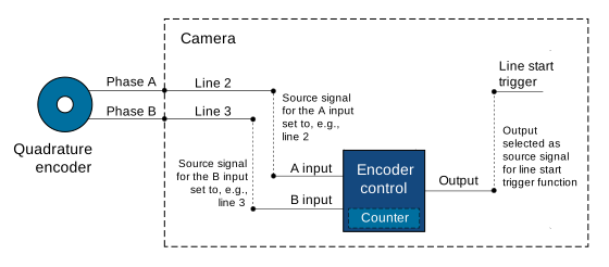
編碼器運動方向#
編碼器可向前或向後移動。為了偵測移動方向,編碼器控制單元會讀取 A 和 B 訊號的上升沿與下降沿的順序。
- 正向運動:A 訊號的上升沿比 B 訊號早 90°。相位順序為 1-2-3-4。
- 向後運動方向:B 訊號的上升時間早於 A 訊號。相位順序為 4-3-2-1。
下圖顯示了與 A 信號和 B 信號的數位訊號電平相對應的四個相位。
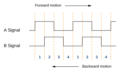
職位Counter#
編碼器控制採用由 A 訊號和 B 訊號驅動的位置計數器。計數器值在正向運動時遞增,在反向運動時遞減。
位置計數器會持續運行。其數值代表自上次重置以來所接收到的輸入訊號數量。因此,計數器數值始終反映目標物體相對於前進或後退運動方向的當前位置。
編碼器模式#
編碼器模式用於控制編碼器控制單元如何計算輸入的編碼器訊號。
四相模式#
四個完整的訊號週期構成一個正交週期。每完成一個完整的正交週期,也就是當 A 訊號邊沿上升時,正交編碼器計數器便會遞增或遞減 1。
「四相模式」相當穩健,能夠過濾掉兩相之間微量的訊號抖動。
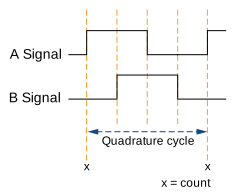
高解析度模式#
在高解析度模式下,每週期的計數會增加至四倍。編碼器計數器會在每個訊號相位(即 A訊號與B 訊號的上升沿與下降沿)時,分別遞增或遞減 1。
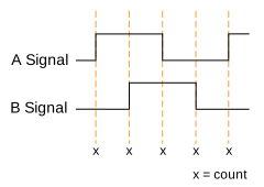
資訊
在「高解析度」模式下無法進行抖動濾波。因此,不建議將「高解析度」模式與 編碼器輸出模式 設定為 Motion 由於兩個相位之間的抖動可能會導致輸出觸發脈衝持續產生。
編碼器輸出模式#
編碼器輸出模式可讓您設定編碼器控制需滿足的條件,以產生有效的輸出訊號。可用的編碼器輸出模式如下:
Motion: 無論運動方向為何,都會產生輸出觸發訊號。DirectionUp: 輸出觸發訊號是在所有位置增量處產生,位於 轉發 方向。向後的運動方向將不予考慮。DirectionDown: 輸出觸發訊號是在所有位置增量處產生,位於 向後 方向。向前運動的方向將不予考量。PositionUp: 輸出觸發訊號在所有情況下都會產生 新 在……的職位 轉發 方向。若編碼器反向運轉,則在再次經過反向起始位置之前,不會產生任何輸出觸發訊號。PositionDown: 輸出觸發訊號在所有情況下都會產生 新 在……的職位 向後 方向。若編碼器反向運轉,則在再次經過反向起始位置之前,不會產生任何輸出觸發訊號。Off: 不會產生任何輸出觸發訊號。
其他參數#
EncoderDivider: 決定生成編碼器輸出觸發訊號所需的編碼器輸入訊號數量。EncoderValue: 取得位置計數器的當前值。此參數為唯讀。EncoderReset: 將位置計數器的當前計數值重設為 0。此操作同時會重設並重新啟動整個編碼器控制系統。重新啟動後,系統會立即開始計數訊號脈衝。
設定Encoder Control#
要設定編碼器控制:
- 將相機中的
EncoderSelector參數設為Encoder1. - 將相機中的
EncoderSourceA將參數設定為其中一個可用的來源訊號,例如:Line2. - 將相機中的
EncoderSourceB將參數設定為其中一個可用的來源訊號,例如:Line3. - 將相機中的
EncoderMode參數設定為以下值之一: - 將相機中的
EncoderDivider將參數設定為所需的輸入訊號數量。 - 將相機中的
EncoderOutputMode根據……的類型設定參數 輸出模式 您要啟用的選項,例如:Motion.
若要將攝影機設定為由編碼器訊號觸發:
- 將相機中的
TriggerSelector參數設為LineStart. - 將相機中的
TriggerMode參數設為On. - 將相機中的
TriggerSource參數設為Encoder1.
範例程式碼#
// Select the desired encoder selector
camera.EncoderSelector.SetValue(EncoderSelector_Encoder1)
// Select line 2 as the source signal for the A input of the encoder control
camera.EncoderSourceA.SetValue(EncoderSourceA_Line2);
// Select line 3 as the source signal for the B input of the encoder control
camera.EncoderSourceB.SetValue(EncoderSourceB_Line3);
// Select the desired encoder mode
camera.EncoderMode.SetValue(EncoderMode_FourPhase);
// Determine the number of input signals needed to generate an encoder output trigger signal
camera.EncoderDivider.SetValue(1);
// Select the desired encoder output mode
camera.EncoderOutputMode.SetValue(EncoderOutputMode_Motion);
INodeMap& nodemap = camera.GetNodeMap();
// Select the desired encoder selector
CEnumParameter(nodemap, "EncoderSelector").SetValue("Encoder1");
// Select line 2 as the source signal for the A input of the encoder control
CEnumParameter(nodemap, "EncoderSourceA").SetValue("Line2");
// Select line 3 as the source signal for the B input of the encoder control
CEnumParameter(nodemap, "EncoderSourceB").SetValue("Line3");
// Select the desired encoder mode
CEnumParameter(nodemap, "EncoderMode").SetValue("FourPhase");
// Determine the number of input signals needed to generate an encoder output trigger signal
CIntegerParameter(nodemap, "EncoderDivider").SetValue(1);
// Select the desired encoder output mode
CEnumParameter(nodemap, "EncoderOutputMode").SetValue("Motion");
// Select the desired encoder selector
camera.Parameters[PLCamera.EncoderSelector].SetValue(PLCamera.EncoderSelector.Encoder1);
// Select line 2 as the source signal for the A input of the encoder control
camera.Parameters[PLCamera.EncoderSourceA].SetValue(PLCamera.EncoderSourceA.Line2);
// Select line 3 as the source signal for the B input of the encoder control
camera.Parameters[PLCamera.EncoderSourceB].SetValue(PLCamera.EncoderSourceB.Line3);
// Select the desired encoder mode
camera.Parameters[PLCamera.EncoderMode].SetValue(PLCamera.EncoderMode.FourPhase);
// Determine the number of input signals needed to generate an encoder output trigger signal
camera.Parameters[PLCamera.EncoderDivider].SetValue(1);
// Select the desired encoder output mode
camera.Parameters[PLCamera.EncoderOutputMode].SetValue(PLCamera.EncoderOutputMode.Motion);
/* Macro to check for errors */
#define CHECK(errc) if (GENAPI_E_OK != errc) printErrorAndExit(errc)
GENAPIC_RESULT errRes = GENAPI_E_OK;  /* Return value of pylon methods */
/* Select the desired encoder selector */
errRes = PylonDeviceFeatureFromString(hdev, "EncoderSelector", "Encoder1");
CHECK(errRes);
/* Select line 2 as the source signal for the A input of the encoder control */
errRes = PylonDeviceFeatureFromString(hdev, "EncoderSourceA", "Line2");
CHECK(errRes);
/* Select line 3 as the source signal for the B input of the encoder control */
errRes = PylonDeviceFeatureFromString(hdev, "EncoderSourceB", "Line3");
CHECK(errRes);
/* Select the desired encoder mode */
errRes = PylonDeviceFeatureFromString(hdev, "EncoderMode", "FourPhase");
CHECK(errRes);
/* Determine the number of input signals needed to generate an encoder output trigger signal */
errRes = PylonDeviceSetIntegerFeature(hdev, "EncoderDivider", 1);
CHECK(errRes);
/* Select the desired encoder output mode */
errRes = PylonDeviceFeatureFromString(hdev, "EncoderOutputMode", "Motion");
CHECK(errRes);
# Select the desired encoder selector
camera.EncoderSelector.Value = "Encoder1"
# Select line 2 as the source signal for the A input of the encoder control
camera.EncoderSourceA.Value = "Line2"
# Select line 3 as the source signal for the B input of the encoder control
camera.EncoderSourceB.Value = "Line3"
# Select the desired encoder mode
camera.EncoderMode.Value = "FourPhase"
# Determine the number of input signals needed to generate an encoder output trigger signal
camera.EncoderDivider.Value = 1
# Select the desired encoder output mode
camera.EncoderOutputMode.Value = "Motion"
您也可以 use the pylon Viewer 來輕鬆設定參數。